Perturbed Blend Bump Mapping
Perturbed Blend Bump Mapping is the technique used in the Voodoo2 Donut Demo. At first it sounds like a weird technique but it actually works. This technique is used mainly for what is called 2D bump mapping. It is used by some 2D drawing packages and used a lot in the good old technology demos.
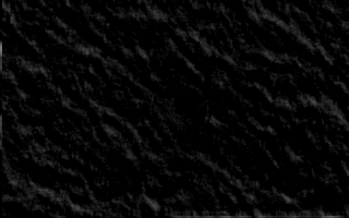
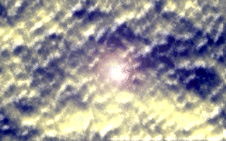
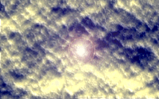
This technique uses a Bump Map (grayscale) and a Texture map. The Bump Map is used twice in this process. The first version of the bump map is used as is. A second version is shifted slightly based on the position of the lights. This shift is done by changing the UV coordinates used by texture mapping so most hardware can do this shift quite easily. These two versions of the bump map are substracted and this give a lightmap. This lightmap is then blended with the texture map and that gives the texture map with the highlights that emulate the bumps. Now this my sound like a bunch of crap to you so lets illustrate it with some examples.
First lets try to do some text that pops out of the screen. The first
image is the colored (well it can be colored) Texture Map :
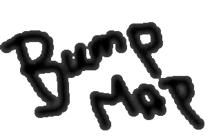
Now we need the Bump Map and the shifted version of the Bump Map :
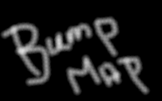
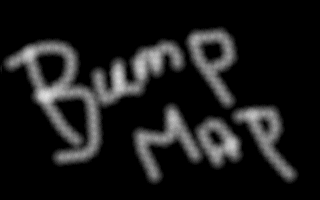
As you can see the shift is very small but when we do the subtraction you
can see that both the images are actually slightly different, the result
of the subtraction gives us the light map :
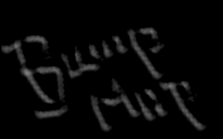
Now all we have to do is combine this lightmap with the original texture
to get the bump mapped version :
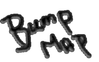
Now when you change the direction of the shift the highlights of the lightmap will change and this gives a realistic bump effect.
There are a couple of problems with this technique. First of all it is hard to use. This is not an algorithm with an easy input believe me it takes quite a bit of experience and trying around before you get a good and accurate effect. Some bump effects just don't work with this technology if you try to make smooth half-spherical bumps on top of a surface then you can forget about it using this technique because it doesn't look right. Another important fact is that the CPU has to calculate the shift based on the position of the polygon and the light source. Now this calculation isn't that complex but it is a calculation. But suppose we want to do bumpmapping of a sphere, so lets say we want to place this "bump map"-text on a sphere then there is a problem. The position of the highlights has been calculated once and is now applied to the whole sphere but because the base polygon changes position this not correct anymore ! So to be accurate you would have to recalculate the shift for every polygon of the sphere this means many calculations and thus more work for the CPU. Another problem with this is that you will see the edges between polygons because the shift is constant in one polygon but is different in the polygons surrounding it, the highlights can thus be quite different and you can see that. Solutions is to use really small polygons but that means again more work... Actually this technique should only be used for flat surfaces like a wall, using this technique on not-flat surfaces gives wrong results (you might not notice we just think the light source is somewhere else).
Here you can see some more images that show you changed highlights :