So when can we see correct V5500 screenshots?
Well Beyond3D is proud to show you one of the first correct
16 bit 4x AA image taken using a special screen capture mode that 3dfx
is placing inside the OpenGL drivers. Ken Dyke from 3dfx wrote some special
code in Glide that can go and read from all 4 sample buffers, combine
them at full precision (thus getting 22 bits of color), and then gamma
correct the image before writing out the .tga file. Using this code, you
get to see exactly what you'd see on the screen. Since 3dfx still uses
Glide as code base this screen-capture code is available to the OpenGL
driver, which can thus capture screen-shots correctly. Unfortunately the
drivers that were send out with preview boards did not contain this code
and as a result screen captures are incorrect. 3dfx will soon send out
new improved drivers together with instructions on how to take correct
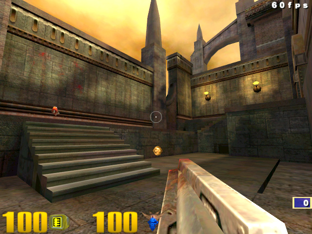
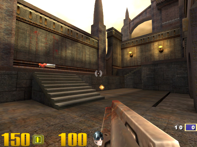
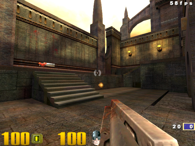
screenshots. Below you find the V5500 shot suffering from truncation as
taken using the old drivers, and also the corrected screenshot taken using
the new driver with special screen capture code. Also included for quality
comparisons is the 16bit GeForce image.
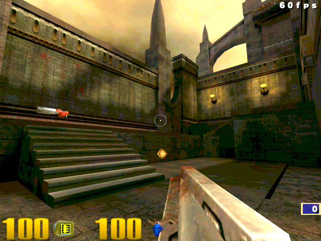
Corrected V5
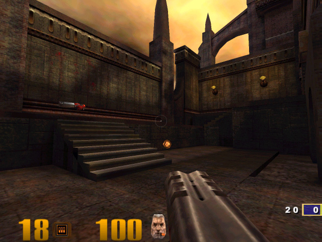
GeForce
In short, we can conclude that all the Quake III Arena screenshots (and almost all other screenshots for that matter) out there that aren't being taken by 3dfx are invalid. So websites like Anandtech, Firing Squad, Reverend etc… are showing incorrect screenshots in most of their Voodoo5 articles/reviews/previews thus far - incorrect as in they do not reflect the true on-screen image quality of the 3dfx V5500 boards. All these shots suffer from data truncation, which results in uniformly colored zones in the images and an overall loss of detail due to a truncation of data during the screen capture phase.
Other influences… Mip Maps
Another factor which can influence the image quality and performance is the Mip Map, and which Mip Map is used for each pixel. Let me first briefly explain what a Mip Map is and why you need them. Imagine the following situation: you want to render a textured square, which is located at a certain distance parallel to the screen. Essentially this means the square remains a square, the only difference is the scale: further away means it gets smaller. Now imagine we use a 256 by 256 pixel large texture map and assume that we position the square in such a way that it has a size of 256 by 256 pixel on the screen. Its obvious that there is a 1:1 relation between the pixels of the texture (TEX-ELS = TEX-ture EL-ement-S) and the pixels of the screen. Now when the square comes closer the texture will zoom in, essentially the same Texel will determine the color of many more pixels. This effect actually creates blurry textures; the same texel is stretched out over a larger pixel zone. Something similar, yet reversed, happens when the square moves further away. The pixel zone on the screen will get smaller and smaller so less screen pixels are available to show the texture information. You could for example say that when the on-screen quad covers 128x128 pixels that you only need 1/4th of the texture data. Now when the square gets smaller and smaller this effect becomes worse, you get continuously less samples inside the texture map. Essentially we have too little pixels to accurately represent the texture on the screen, we get aliasing! Aliasing will show itself as flicker and crawling pixels inside the texture. A simple example is this: imagine a striped texture alternating from black to white, so one line is black and one line is white of the texture. When your onscreen resolution matches your texture resolution the strip pattern will show up perfectly, when you move further away and the size shrinks the strip pattern will be destroyed, you can no longer represent the uniform strip pattern correctly and all kinds of odd artifacts will pop-up. Another issue is bandwidth efficiency. As you know, 3D cards rely on a texture cache to reach their claimed specs. This cache actually relies on the fact that the same texture data will be re-used to render several pixels, essentially this means the hardware is hoping for “zoomed†textures rather than “shrunken†textures. When the polygon is small, the texture data re-use is close to zero which leads to very poor performance due to the fact that memory cannot supply data fast enough. Using Mip Maps can solve both of these issues, aliasing and poor data re-use. Mip Maps are down sampled versions of the original texture. So instead of having one 256x256 texture you also have down sampled version of 128x128, 64x64, etc… all the way down to 2x2 and 1x1. The advantage this gives is that aliasing is removed, since the lower Mip Levels are created using a low-pas filter (meaning that high frequency effects like the strip pattern mentioned below are smoothed out). The data access patterns and texture data re-use is also much more optimal since you can always select a Mip Level (a certain size of Mip Map) so that you are always in the “zoomed†case where there is data re-use. Mip Maps can obviously have a large influence on image quality. The parameter that selects the level has a major impact especially.
Mip Map Level Bias
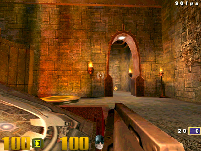
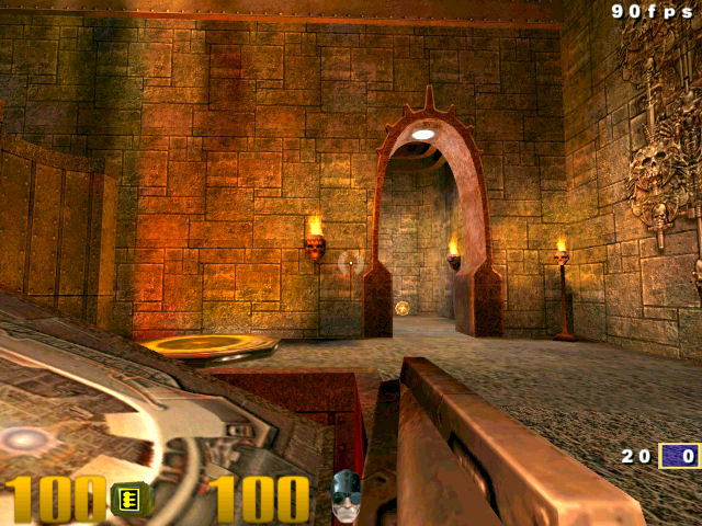
Selecting the correct Mip Level (size of texture) to use is quite tricky. You need to balance between image quality and performance. Let me clarify, for optimal performance you want “zoomed†in textures, so a lot of data is re-used, giving you high cache efficiency and high frame-rates. However “zoomed†textures tend to look blurry, so if you always select a low Mip Level (lower resolution one) then you won’t see a lot of texture detail. Always selecting a high Mip Level will give you lots of details, but your cache efficiency will drop resulting in lower frame rates. Also, the risk of Aliasing is increased; high frequency textures might show flickering and crawling artifacts. Finding the correct balance is not easy, but usually companies opt for a more zoomed blurry look since it gives better performance. The shots below were created using a “hackedâ€, or “modified†OpenGL driver. The “hack†or “modification†allows us to change the Mip Level Bias. This Bias value allows us to opt for sharper or blurrier textures. Essentially we change how the hardware selects the correct Mip Level. The screenshots below are taken on the 3dfx V5500 using this hack. Notice the difference in texture detail:
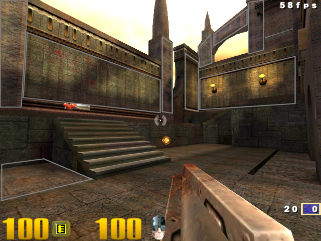
Normal Glide3x.dll shot
Hacked Glide3x.dll shot
An even more convincing example is shown below in these two images. Note especially:
- The entire front wall
- The jump pad
- The right side wall, towards the corner where it meets the front wall
- The walls beyond the arch
Default LOD bias settings
Hacked LOD bias settings
We personally believe that the Mip Level Bias settings used by 3dfx in the standard drivers are too conservative, meaning that textures are set blurrier then necessary. Of course, this is logical when thinking about benchmarking performance. Officially Microsoft defines the correct Mip Level Bias, which can even be changed by games and applications, but this standard defined setting is thus a bit blurry. Luckily 3dfx is considering adding a Mip Level Bias Slider in future drivers, such a slider would allow you to select sharper textures or extreme blurry ones. The sharp textures will give high quality graphics at the expense of performance, the level of which depends on the amount of bias applied while the blurry setting will give high performance. 3dfx will also include a default position, which should be used when benchmarking and comparing with competitors. The benchmark issue is rather big for 3dfx, since opting for sharp textures will reduce performance, which would give competitors an unfair advantage. However, we would assume that 3dfx will have a “Default†setting for this for the purpose of “uniformity†in benchmarking. In our testing, selecting sharper textures gave a frame rate hit below 10%. We are confident that many users will find this higher quality setting worth the performance hit, particularly since lower, non-bandwidth limited resolutions don’t even suffer a hit. Using the sharper setting together with 4x RGSS gives extremely high quality images as the example images above illustrate. However, setting the Mip Level Bias too high can introduce artifacts into the image. The impact of these is lessened somewhat by FSAA, but not entirely.