Specular Light
Specular lighting identifies the bright specular highlights that occur when light hits an object surface and reflects back toward the camera. It is more intense than diffuse light and falls off more rapidly across the object surface. It takes longer to calculate specular lighting than diffuse lighting, however the benefit of using it is that it adds significant detail to a surface.
The formula for Specular Lighting is defined as follows:
| Specular Lighting = Vs*sum[Ls*(N.H)P] |
The sum is included for multiple light sources. Vs is the Specular colour of the material, Ls is the Colour of the Specular Light Source, the product of these 2 terms again forms the basic light behaviour. This basic behaviour is multiplied with a factor defined as the dot product between N and H raised to the power P. N is the normal vector of the vertex as defined before. H is the Half Way Vector. This halfway vector (H) exists midway between the vector from an object vertex to the light source and the vector from an object vertex and the camera/eye position. The figures below illustrate this half way vector.
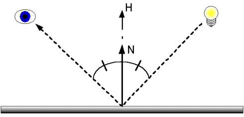
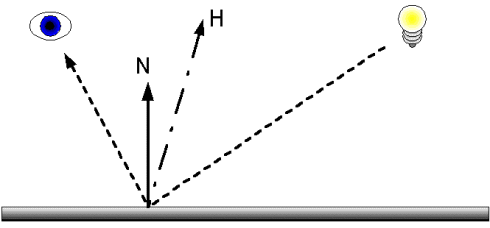
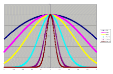
What you notice is that if the eye vector and the light vector take the form of a reflection then the Normal and the Half Way vector become one and the same meaning that the cosine value of the dot product will be 1. So the Specular power is strongest when you have a direct reflective light path. Now the power factor P has an influence on the result of the dot product. If we assume that N and H have a length of 1, then the dot product is a simple cosine function. The figures below show what happens if you raise a cosine to different powers P.
Notice how the rounded cosine shape turns in to a narrow peak when higher powers are used. This narrowing effects is used to model correct Specular behaviour, Specular reflections only takes place for a very small angle range where they contribute to generate a bright hotspot, for all other angles the impact of Specular lighting is almost non-existing. By raising the cosine to a high enough power this effect can be achieved. The figure below illustrates these concepts:
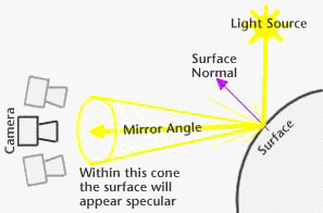
At the end of this section is a java applet that allows you to play with the factors influencing specular lighting, play with the power P to see the impact on the specular contribution.
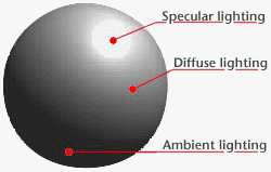
The following illustration show the 3 components (Ambient, Diffuse and Specular) we have so far discussed:
Emissive Light
Emissive lighting is light that is emitted by an object, for example, a glow. This factor is modelled by a single factor:
| Emissive Lighting = Me |
Where Me is the Materials emissive colour. This factor is rarely used.
Java Applet
The Java Applet that enables you to experiment with the various types of lighting discussed here can be found here. Experiment with it to see what elements each of these types of lighting bring into a 3D scene.

