TnL Pipeline
The fixed function Transform and Lighting Pipeline is a piece of hardware that allows fast execution of the principles we described before. It allows the fast transformation and lighting of a vertex, which results in the transformation and lighting of the triangle it is part of, which again results in the transformation of the object formed by a group of triangles, and all of this results in a lot of objects that create the game scene.
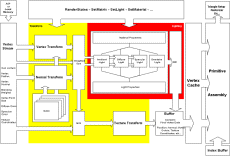
Below you can see a very simplified diagram of a fixed function TnL Pipeline:
Looking at this diagram there is a single main input defined as the vertex stream and a single output buffer, there are some other inputs which act on the behaviour of the different elements of the fixed function hardware I’ll call these inputs registers. These registers are updated by the driver based on functions called by the program, such as setting render states, matrices, light, material properties.
The vertex stream contains the actual input of the hardware, this input provides all the base data that is needed to do the transform and lighting of a vertex. So obviously this data contains the vertex position, one or more texture coordinate sets for transformations and for lighting the vertex normal, diffuse and specular colours. There are some other possible elements like Blending Weights (more on those later) and Vertex Point Size which is used to define point sprite size. Point sprites are special quads that are always parallel to the screen they are defined by a single vertex and a size (which can change per point sprite and thus per vertex). This input data can be seen as a stream of packets, each packet contains the full vertex description, these packets are grouped together in a stream (so a stream of lots of vertices all waiting to be transformed and lit) which can be fed into the hardware from local video memory or through AGP. Each packet in this stream has a number attached to it, a unique id, these numbers are referred to as an index. As you know vertices form triangles which form objects. To build triangles from the vertices an index list is used, this list contains the unique id numbers of the vertices that form a group of triangles that form the object. This index of vertices is also used to determine which vertex has to be pushed into the TnL unit, since not every vertex in the buffer has to be transformed (a buffer can contain multiple objects) and some vertices might even be TnL-ed multiple times.
The output buffer contains the final vertex data; this data is stored in the vertex cache. The output data is cached for 2 reasons. The first reason is that this “post TnLâ€-cache is actually the input buffer of the primitive assembly block. Primitive assembly builds triangles from the output vertex data using the index list mentioned in the previous paragraph. For example say we want to build a quad, formed by 2 triangles. The Vertices with ID 1, 2 and 3 form the first triangle, the next triangle of the quad can be formed by the vertices with ID 2, 3 and 4. Notice how vertex 2 and 3 are shared by the 2 triangles that form the quad. If we did not have a large enough buffer these vertices would have to be transformed twice. For example if there was only a single entry buffer then the TnL unit would have to transform vertex 1,2 and 3 and then again vertex 2 and 3 followed by the new vertex 4. Because there is a buffer the result of transforming vertex 2 and 3 can be re-used which improves speed (no need to do the same work twice or more). The vertex cache on its own could be a full article but this short introduction should give you at least some clue about why its there and how it works. Primitive assembly builds the triangle which is then send of to the setup (including clipping) and rasterizer part of the hardware which is not discussed in this article.
Now that we have defined the input and output of our TnL Block we can start looking at the actual Fixed Function TnL Pipeline. This pipeline does exactly what its name says: it executes a “single fixed functionâ€, namely: “transform and light each vertex based on the state of the registersâ€. This pipeline can do nothing but the fixed function it was designed to execute.
I explained how transformations can be done using matrices and this is exactly how the fixed function pipeline works for transforming vertex, normal and texture coordinates. Using API calls its possible to set all the different transformation matrices (from object space – axis relative to object, to world space – axis at some point in the world, to camera space – axis at the camera position, - projection to screen space) these matrices are set in the registers of the chip. These registers are then used to transform the input data from the vertex stream and results are passed into the output buffer and to the lighting unit. In the lighting section I described the basic equation which form the lighting model, these equations require input values which are again set using instructions and stored in the registers. These registers are read by the lighting unit which applies the correct mathematics and places the results in the output buffer.
I won’t go into detail about how the transformation and lighting blocks work.
More details about actual low level hardware implementations will be given in
the vertex shader section. The essential bit is that this whole design is
pipelined. The impact and meaning of pipelining is described next.

